HEATRECOVERY.PRO – Rewolucja w odzysku ciepła od sprężarek

  • Polski
  • English

REVOLUTION IN COMPRESSOR HEAT RECOVERY

We are at the forefront of innovation in compressor heat recovery. By advancing innovative solutions, we have developed equipment that allows for the most efficient recovery of heat generated by industrial compressors on the market.

HEAT RECOVERY WHY IS IT WORTH IT?

Investing in energy savings leads to better financial performance for your business.

Heat recovery is an excellent way to meet emission standards.

Heat recovery always pays off.

ANIMATION SEE HOW IT WORKS

Play Video

Innovative and most advanced compressor heat recovery module.

powERpack is a revolutionary product developed as part of an R&D project in partnership with the National Centre for Research and Development (NCBR). At the heart of the powERpack lies innovative compressor heat recovery technology, tested in rotary screw and vane compressors in almost 6,000 measurement runs across the full temperature range. The developed mathematical models of the physical properties of the compressors provide a solid foundation for the safe and efficient recovery of heat in performance heating parameters.

The most effective control algorithm for heat recovery has been selected out of 21 control methods in almost 2,000 measurement runs. This allows the powERpack to recover heat efficiently, with a well-documented heat exchange efficiency of more than 90%. On top of this, the powERpack guarantees the lowest oil-side pressure drop in its class! With powERpack, users of industrial air compressors save on energy costs and protect the environment while improving the efficiency of their heating systems. A prime example of how innovative technological solutions can make a positive impact on our lives and the environment.

A controller with a touchscreen control panel is responsible for implementing the most effective control algorithm for compressor heat recovery. It allows the entry of the desired receiving temperature and protects the compressor from overheating and overcooling. On top of this, it monitors the operating status of the actuators and has a built-in Ethernet interface. The controller also calculates the amount of heat energy received. Readings from the water-side and oil-side temperature sensors enable control of the heat recovery process to ensure efficiency and safety.

get to know watch the simulation

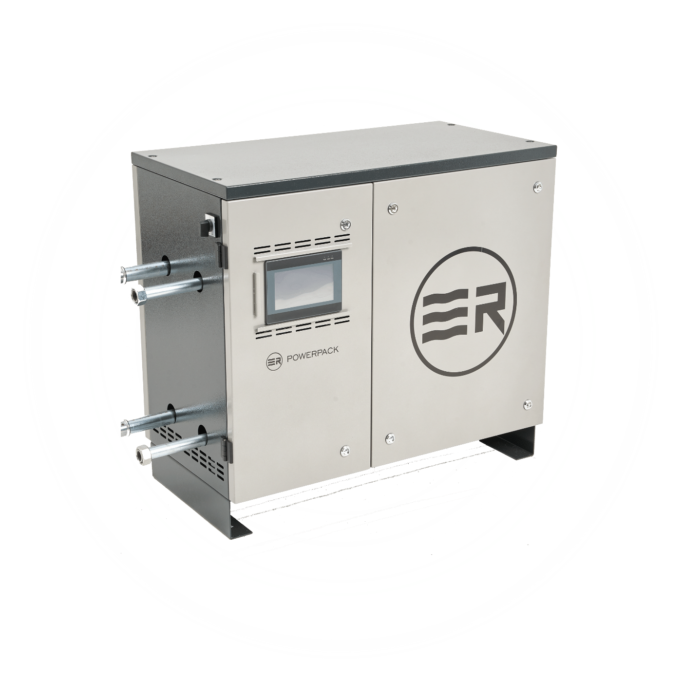
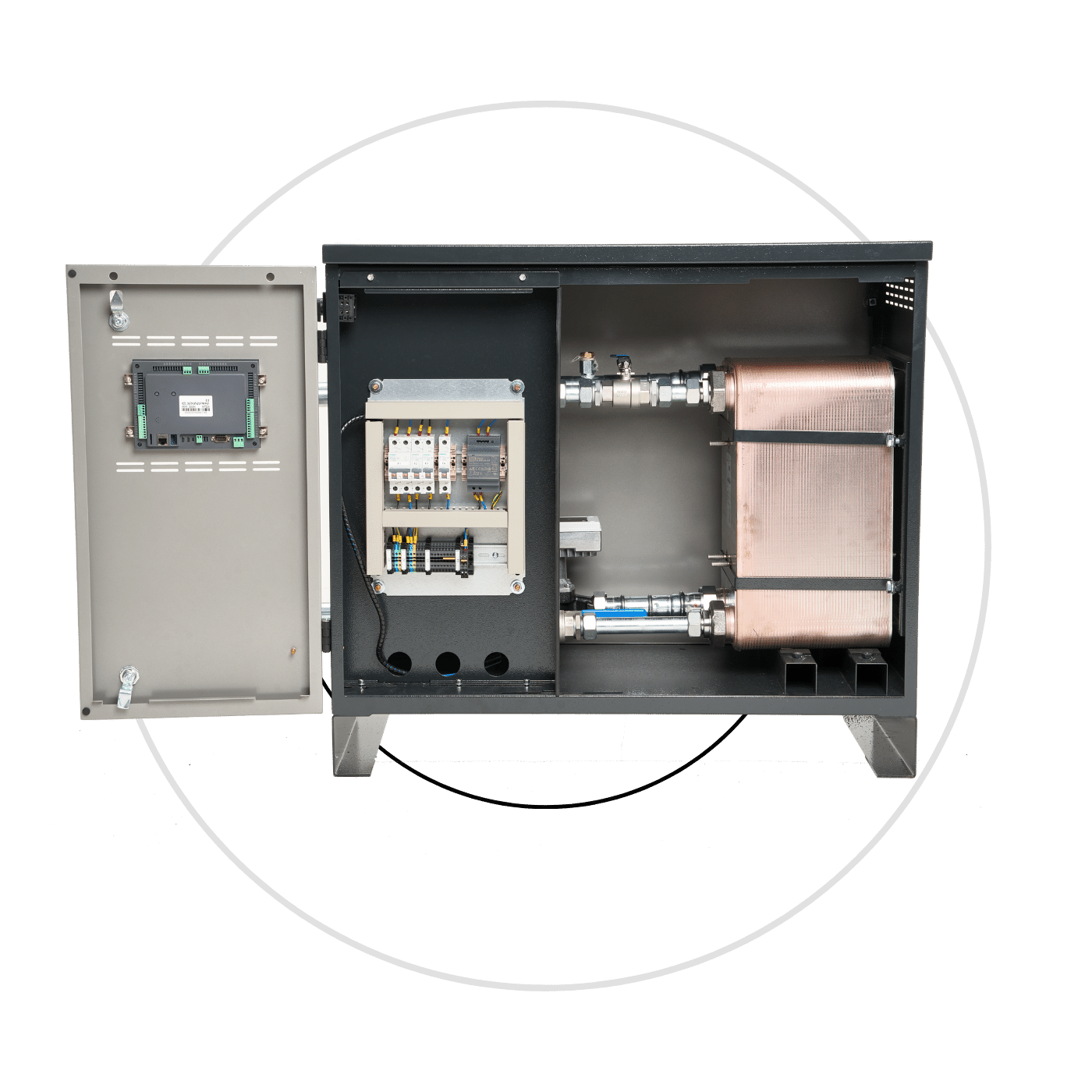
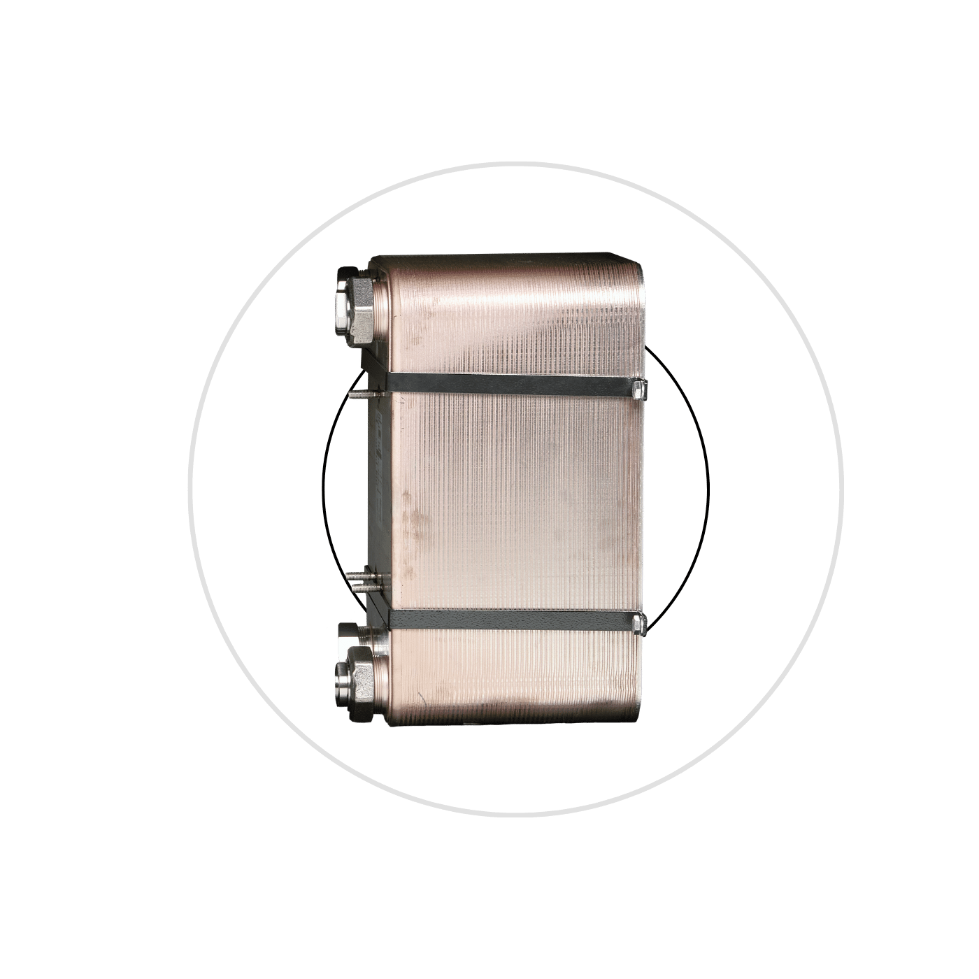
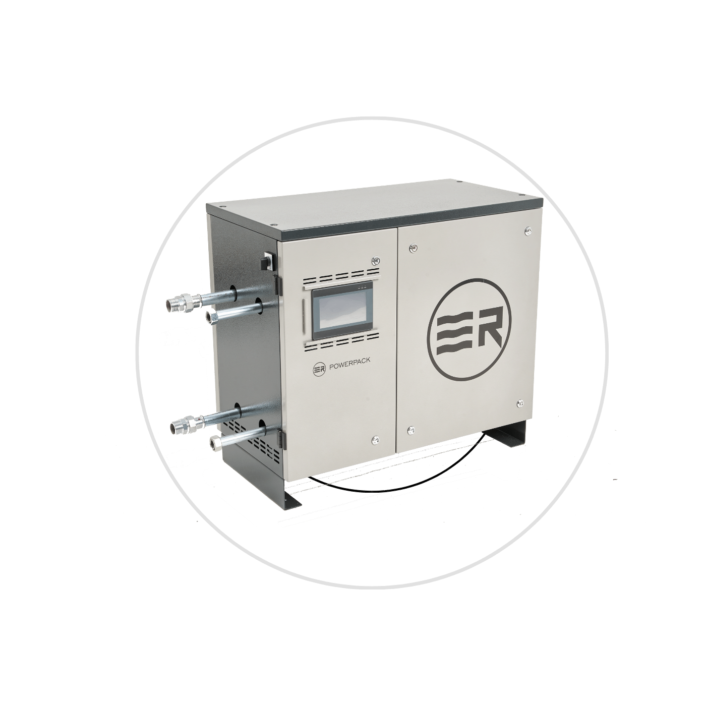
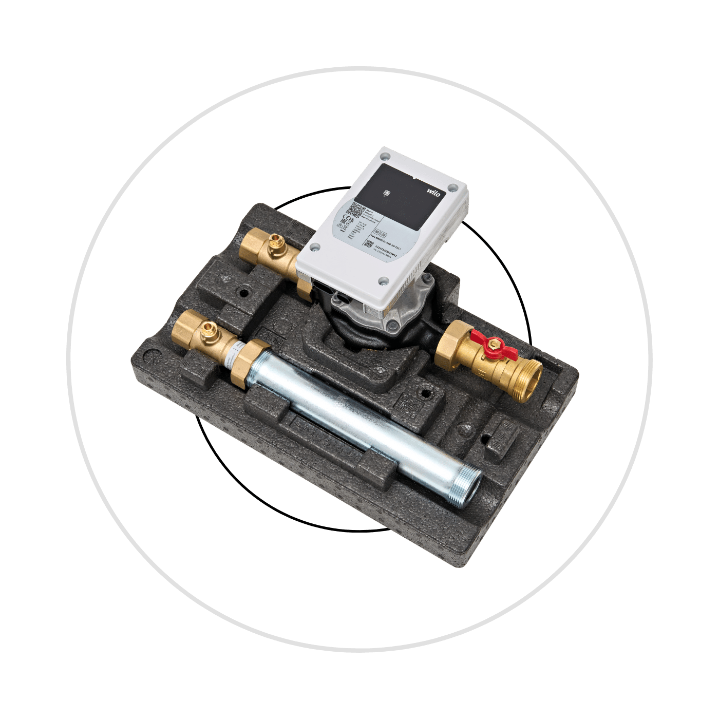
A standard heat recovery system from the compressors adds a three-way thermostatic valve at the heat exchanger outlet. The valve provides protection against oil overcooling. The oil at the injection to the compressor unit should exceed 55°C. Lower-temperature oil would pose a hazard in terms of condensate precipitation from the compressed air right in the screw unit or in the separator, which should only occur in the aftercooler. With this hydraulic solution, we are dealing with a system of two thermostatic control valves in series (a valve at the recovery exchanger and a cooler valve). Control-wise, such a system is difficult to regulate, with the need for feedback on the position of the two valves so that they do not interfere with each other. Besides the aspect of the mutual interference of the two valves, another important aspect is the time constant of the thermostatic valves. This is the parameter which determines the inertia of the valves, or more precisely the time it takes for them to make a full stroke – from a closed position to a fully open one. Thermostatic oil valves in compressors have a time constant of approx. 20s. Combined with an oil temperature rise time in the compressor of 0.5°C/s, these valves are fast enough in compressors without a heat exchanger and allow their correct operation. The above-mentioned figures are different in compressors equipped with a heat exchanger. The temperature difference between the thermostatic valve cartridges is 20°C (55°C – valve at the exchanger, 75°C – valve at the cooler). In the event of oil overcooling in the exchanger, the thermostatic valve bypasses the oil outside the exchanger. Such overcooling is not unlikely in a water system without overriding control of the compressor heat recovery system. Once the fixed-speed compressor is relieved of load, or the variable-speed compressor reduces its speed, the amount of heat energy to be collected decreases, so the fixed-speed pump generates an oversized flow of water by collecting more energy from the oil than is available in it. When the compressor reloads, the oil rapidly increases its temperature. Once 55°C is reached, some of the oil begins to flow through the heat exchanger, pushing out the oil cooled by the lack of regulation. As a result of the mixing of the two streams (the warmer one from the separator and the overcooled one from the exchanger), the valve at the oil cooler fails to see the temperature rise of the oil in the separator. Thus, the valve at the oil cooler, depending on the capacity of the exchanger, sees a constant temperature of approx. 55°C for 30-35s, where under normal conditions (without the exchanger with an additional thermostat) it would see a temperature rise identical to that in the compressor unit. Once this time has elapsed, there is an increase in the oil temperature value (55°C-75°C) in the vicinity of the oil cooler valve in approx. 5s. Referring to the time constant values of the thermostatic valves – the valve at the cooler, due to the time delay introduced by the valve at the exchanger, turns out to be too slow. Consequently, oil that is too warm will reach the compressor unit, leading to the compressor shutting down due to overheating. To summarise the above cycle of events, it is important to note that, under the right set of circumstances in the operation of a heat recovery system, the valve responsible for not overcooling the oil is co-responsible for its overheating.

The solution to the phenomenon described above is to eliminate the control valve at the heat exchanger from the heat recovery system. The temperature of the oil flowing through the heat exchanger can be controlled at all times by regulating the secondary – water – side. Thanks to the available technology of variable speed pumps and linear control valves with fast actuators, the change in flow on the water side can follow the rate of change on the compressor side even with varying conditions on the water side occurring at the same time. Thanks to the patented solution used in the Powerpack and Powercontrol, oil flows directly from the separator through the exchanger at all times. The secondary side control is responsible for temperature regulation at the exchanger outlet (similar to the function of the three-way valve at the exchanger). Thus, by controlling the water flow, we eliminate the possibility of the oil overcooling, enabling continuous cooling of the oil under the overcooling limit, i.e. removing all the disposable heat energy carried by the oil.

CONTACT US GET QUOTE ON THE INSTALLATION

Take a few minutes to complete the form and get an installation quote within a few working days.

heat recovery calculator

Savings [MWh]
Savings [EUR]
Reduction of manual CO2 emissions (tons per year)
Coal heating
Gas heating
Electric heating